Hardware Architecture Breakdown
1. Overview
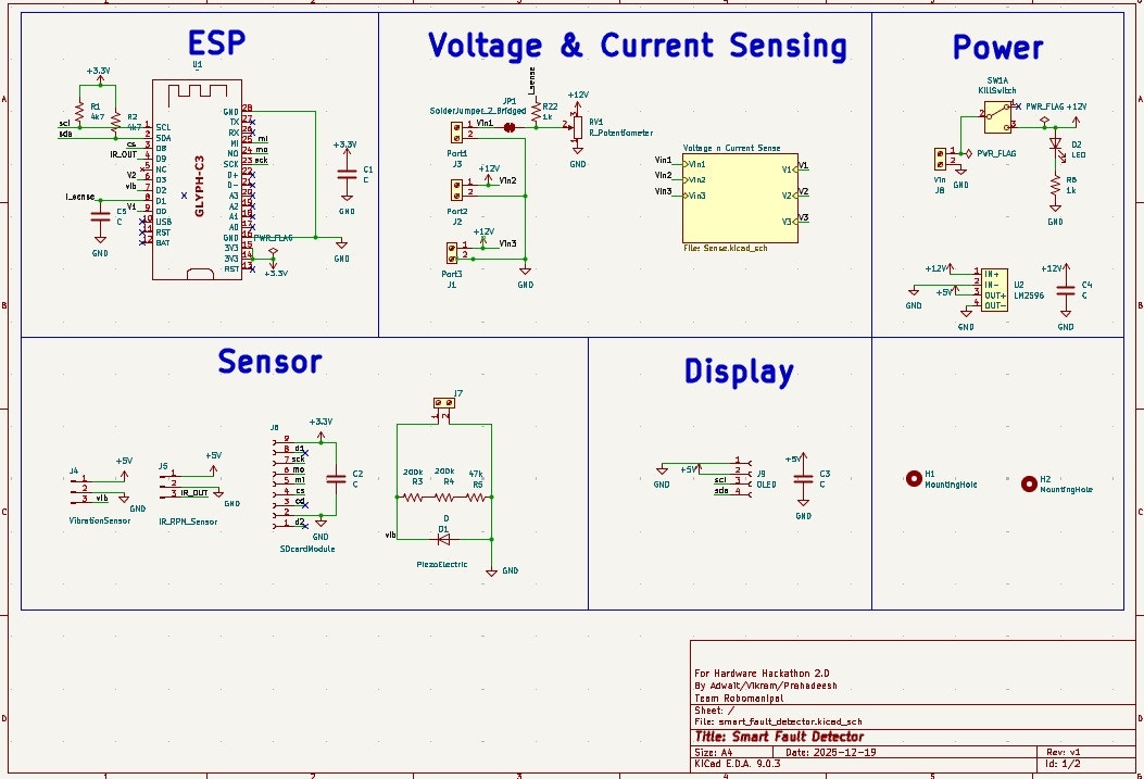
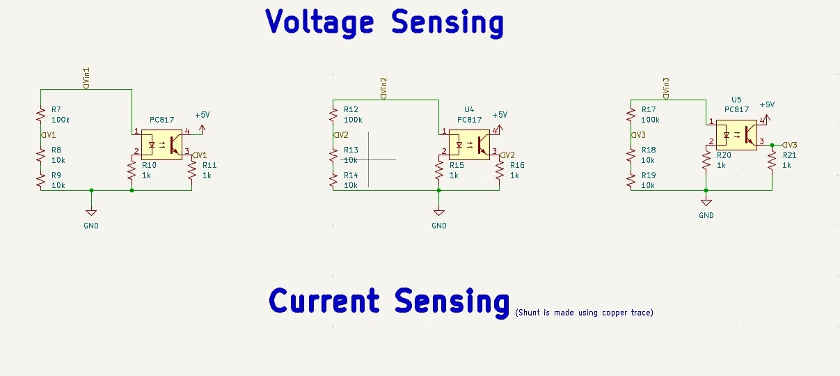
The Smart Fault Detector is a modular health-monitoring device designed to detect actuator faults and failures in mission-critical environments such as rockets, rovers, and base stations. It fuses electrical telemetry such as voltage and current drawn by the actuator with mechanical data such as rpm and vibration around the actuator to determine if an actuator is operating within safety parameters and predicts the estimated time to failure.2. Schematics
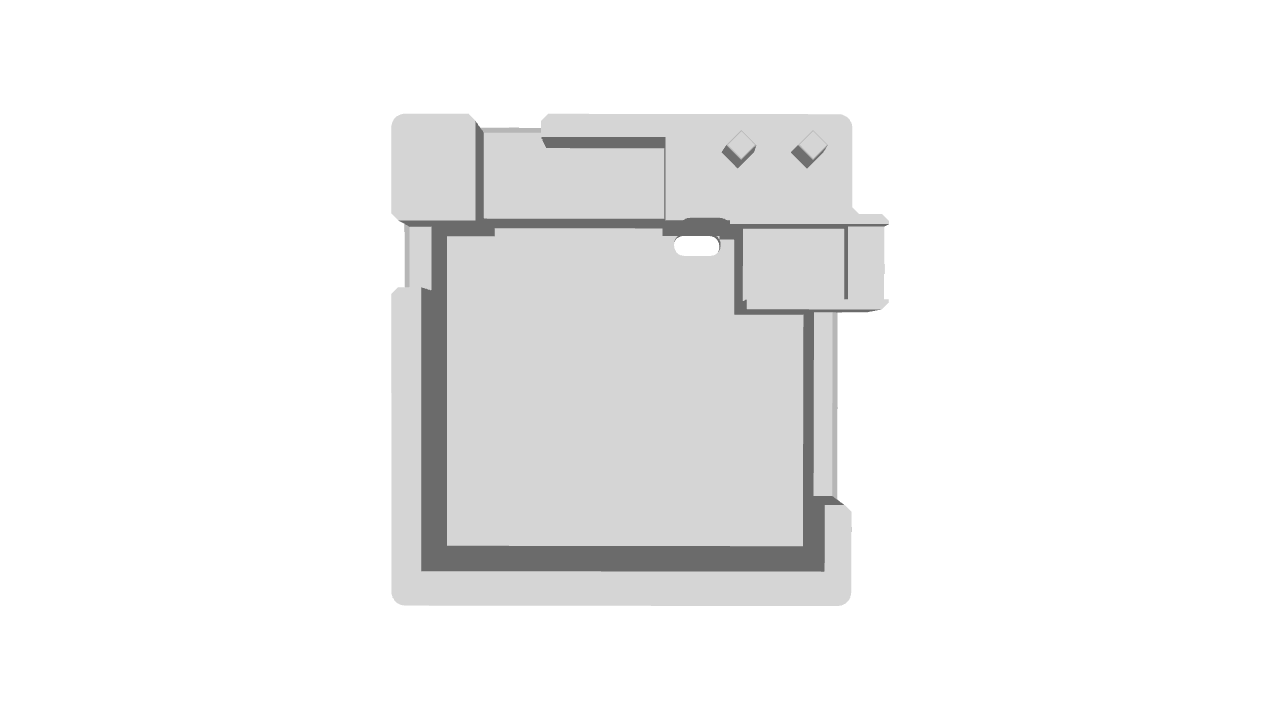
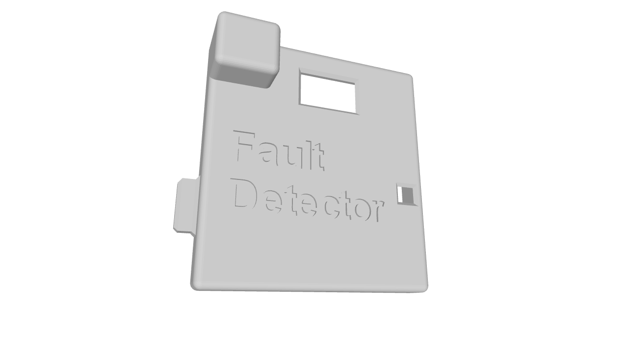
2.2 3D Printed case
3. Key Features
- Current sensing - Upto 2A using the PCB trace shunt for 1 channel.
- Voltage Sensing - Using voltage divider/using optocoupler (for electrical isolation)
- Tachometer - To measure RPM of the actuator
- Vibration Sensor - To measure mechanical degradtion due to vibrations
- Dashboard - ESP32 broadcasts the previous logged and live data using WiFi
- A SD card is present to log data and can be used to debug after major failure
4. Application
Any system which needs to be robust and needs maintenance - like rovers and other AGV (Autonomous Guided Vehicles) etc5. Modules required
- GLYPH-C3 (ESP32-C3) Development Board
- MicroSD Card Module
- LM2596 Buck Converter
- PC817 Optocoupler
- IR Sensor
- Piezoelectric Element
- 0.96-inch OLED Display